Replacing ZFS pools with boot partitions (In Proxmox)

I’ve created this document in order to have a clear guide to replace boot disks in a ZFS pool for proxmox, basically because the one on their documentation was not completely clear for me.

Source documentation: https://pve.proxmox.com/wiki/ZFS_on_Linux

In my case I was dealing with a Raid1 ZFS pool, both with bootable drives.

I wasn’t aware these drives had 3 partitions, which I had to replicate to the new drive in order to perform the proper replacement.

We replicate these partitions with the following commands:

sgdisk <healthy bootable device> -R <new device>    -  (use /dev/diskname)

sgdisk -G <new device>  - (use /dev/diskname)

The the second command will make sure the new partitions that have been copied from the remaining surviving drive, have unique GUIDs, it’s a bad idea to have disks with cloned GUIDs.

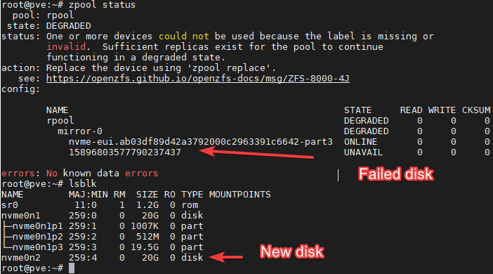
In the example above we see that Nvme0n1 is the remaining disk in the array, which is in good state.

Nvme0n2 is the new one, the one we are going to used to replace the failed one.

Knowing this we run the following commands:

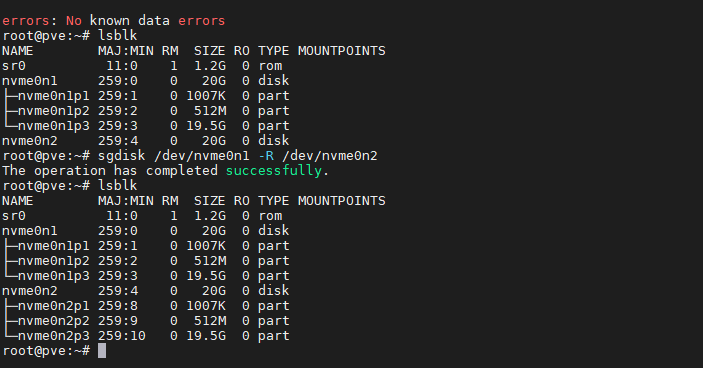
sgdisk /dev/nvme0n1 -R /dev/nvme0n2

sgdisk -G /dev/nvme0n2

The last command should output: The operation has completed successfully.

After, we should see the partitions replicated:

Now, we need to add the partition 3 to the ZFS pool array. Previously I made the mistake of adding the complete disk, which would destroy the partitions created and will not let you install the boot partition into the disk.

Avoid that mistake, what we need to add is the disk to the array, not the complete disk.

Lets move now to identify the partition ID we want to replicate:

ls -lh /dev/disk/by-id/

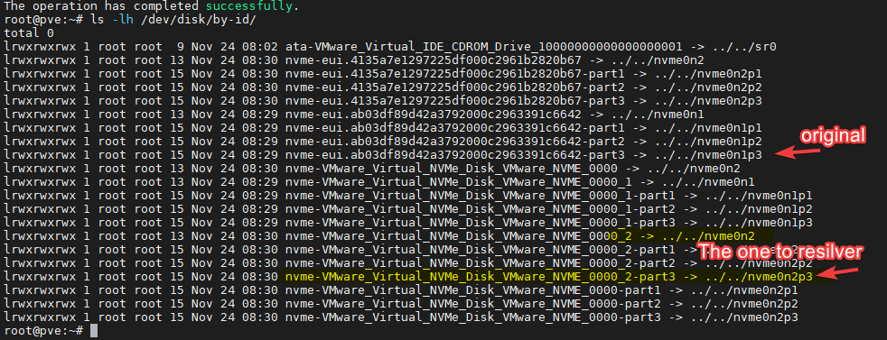
We know the new disk is the nvme0n2, and we know the partition is nvme0n2p3, so the ID we’ll use now its:

nvme-VMware_Virtual_NVMe_Disk_VMware_NVME_0000_2-part3

The command we need to now follow its:

# zpool replace -f <pool> <failed disk id> <new zfs partition>

From the first image in the document, we know the failed partition has this ID: 15896803577790237437

The resulting command should be:

zpool replace -f rpool 15896803577790237437 nvme-VMware_Virtual_NVMe_Disk_VMware_NVME_0000_2-part3

Do NOT do it like this:

zpool replace -f rpool 15896803577790237437 /dev/nvme0n2p3

The zpool replace command will start a resilvering process, which you should monitor until its 100% complete before moving forward.

We can monitor this process with the command:

watch zpool status -v

Once this process is completed, you can move on to install the boot files in the p2 partition for the drive

First we need to validate if we are using UEFI or GRUB with the following command:

proxmox-boot-tool status

You need to validate if the system says you are booting with legacy bios or UEFI.

# proxmox-boot-tool format <new disk's ESP>

In the example we are using, we know the boot partition should be /dev/nvme0n2p2, so following the example above the next command should be:

proxmox-boot-tool format /dev/nvme0n2p2

# proxmox-boot-tool init <new disk's ESP>  [grub] (optional)

After formatting the partition, we proceed to install the boot files, if we are using grub the command should be:

proxmox-boot-tool init /dev/nvme0n2p2 [grub]

If we are using UEFI, the command should be:

proxmox-boot-tool init /dev/nvme0n2p2

Then we proceed to clean the previous boot entries that are no longer relevant with the following command:

proxmox-boot-tool clean

You can now proceed to validate if the boot partitions have been correctly installed with the following commands:

proxmox-boot-tool status

cat /etc/kernel/proxmox-boot-uuids

The output should look similar to this (Legacy Bios example)

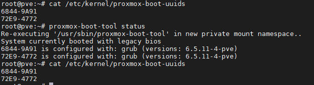
Since this is a raid1 pool with 2 disk, we should only see two lines per output.

You should now be able to boot from both drives!

How to create VLANs with Mikrotik – Part 1

I’ve found when you begin to work with Mikrotik, creating and handling VLANs can get a bit daunting (Especially when you come from a Cisco background) so I’ve decided to make a 3 part tutorial on how to create VLANs in Mikrotik:

Part 1: The easy and clunky way.

Part 2: The right way without using the chip switch

Part 3: The right way to use the chip switch.

This part is for those who need to use VLANs in a home environment and just want to get it done and out of the way. I’ve called it the clunky and easy way because even though it works, It’s not the proper way of handling and creating VLANs in Mikrotik routers, so this is mostly for beginners and home users. But it works. It’s clunky because you’ll need to create a bridge for every VLAN you have.

I’ve found no downsides while using this method in a home environment or a home lab, I haven’t tried this method in production environments and I strongly advise against it, mostly because it can get overly complicated as it grows and you could overutilize the CPU of your router when you could be using the switch chip.

In this scenario, I’ll be configuring over GNS3 a Mikrotik router with 3 VLANs, and a trunk port, and I’ll be connecting it to a Cisco Switch just to prove that it works.

Each device will have devices connected to it working with different VLANs.

I’ll be also sharing the config files for the Mikrotik and the cisco switch. Please take into consideration that there is no firewall nor security configured anywhere in this lab, so don’t try to apply this method blindly without setting up a firewall or password protecting your devices.

I’ll be also assuming you know how to read the config files on your Mikrotik devices and Cisco Switch and you know how the configuration on Mikrotik relates to the GUI.

Now for starters on the Mikrotik, let us begin with the Trunk Port.

Some people like to create the VLANs directly on a physical interface, I rather create the VLANs over a Bridge which I usually call the “Trunk Bridge” this is because I may want to have more than one trunk port.

I will begin with a clean slate configuration that only has a DHCP client configured the ether1.

To begin, we’ll create Bridge and then attach it to the interface we want to work with. I’ll be creating a bridge called “bridge-trunk” that will be attached to the ethernet interface 5 of the Mikrotik:

For this we’ll type on the Mikrotik’s terminal:

/interface bridge
add name=bridge-trunk

/interface bridge port
add bridge=bridge-trunk interface=ether5

And we’ll see on Winbox something like this:

Now that we have our trunk bridge, we can create our VLANs and attach them to our trunk bridge.

/interface vlan
add interface=bridge-trunk name="vlan 2" vlan-id=2
add interface=bridge-trunk name="vlan 3" vlan-id=3
add interface=bridge-trunk name="vlan 4" vlan-id=4

And we’ll get something like this:

Now, we’ll create a bridge for every VLAN we are going to use and we’ll connect it to each VLAN we’ve created, and then, we’ll connect them to our desired ports.

/interface bridge
add name=br-vlan2
add name=br-vlan3
add name=br-vlan4
/interface bridge port
add bridge=br-vlan2 interface="vlan 2"
add bridge=br-vlan3 interface="vlan 3"
add bridge=br-vlan4 interface="vlan 4"
add bridge=br-vlan4 interface=ether4
add bridge=br-vlan3 interface=ether3
add bridge=br-vlan2 interface=ether2

From here, we already have our access ports and trunk port working, however, we still need to configure IPs and the DHCP server in order for everything to work properly.

In case you’re following this in a physical or virtual lab, I’ll leave the rest of the commands and the configuration file for both the Mikrotik and Cisco Switch.

In order for our connected devices to work, we need to set up the IP of the bridge interfaces for each VLAN, a DHCP Server, and our NAT.

/ip address
add address=10.0.2.1/24 interface=br-vlan2 network=10.0.2.0
add address=10.0.3.1/24 interface=br-vlan3 network=10.0.3.0
add address=10.0.4.1/24 interface=br-vlan4 network=10.0.4.0
add address=10.100.0.1/24 interface=bridge-trunk network=10.100.0.0

/ip pool
add name=dhcp_pool0 ranges=10.0.2.2-10.0.2.254
add name=dhcp_pool1 ranges=10.0.3.2-10.0.3.254
add name=dhcp_pool2 ranges=10.0.4.2-10.0.4.254
/ip dhcp-server
add address-pool=dhcp_pool0 disabled=no interface=br-vlan2 name=dhcp1
add address-pool=dhcp_pool1 disabled=no interface=br-vlan3 name=dhcp2
add address-pool=dhcp_pool2 disabled=no interface=br-vlan4 name=dhcp3

/ip dhcp-client
add disabled=no interface=ether1-wan
/ip dhcp-server network
add address=10.0.2.0/24 dns-server=10.0.2.1 gateway=10.0.2.1
add address=10.0.3.0/24 dns-server=10.0.3.1 gateway=10.0.3.1
add address=10.0.4.0/24 dns-server=10.0.4.1 gateway=10.0.4.1
/ip dns
set allow-remote-requests=yes
/ip firewall nat
add action=masquerade chain=srcnat

Now we can see PC 1 and PC 8 which are on different VLANs and on each end of the setup being able to talk to each other and to get Internet connectivity

And if you would like to study each configuration, here is the ending configuration file for the Mikrotik and the Cisco Switch.

If you are interested in the GNS3 lab, send me an email and I’ll gladly share it with you.

I hope this has been informative for you, happy trails!