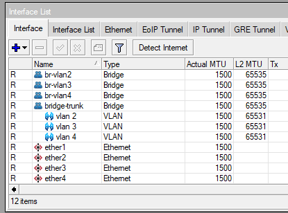
In a previous post I covered the easy way to create VLANs on MikroTik — one bridge per VLAN. It works, it’s great for learning, but it doesn’t scale well and it’s heavier on the CPU than it needs to be. If you haven’t read it, you can find it here.
This post covers the proper way: bridge VLAN filtering. One bridge, one VLAN table, everything in one place. Understanding the easy way first makes this much easier to appreciate — but you don’t need it to follow along.
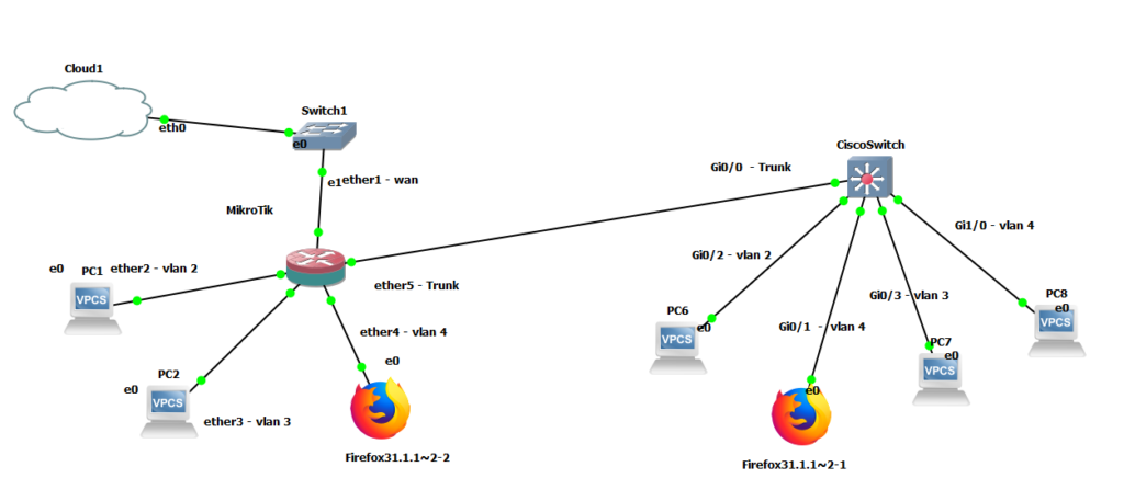
The topology is the same as in the previous post: a MikroTik router connected to a Cisco switch via a trunk port, three VLANs, devices on each VLAN getting DHCP and internet access.
How Bridge VLAN Filtering Works
Instead of creating a separate bridge for each VLAN, we create a single bridge and enable VLAN filtering on it. The bridge then maintains a VLAN table that controls which ports carry which VLANs — tagged (trunk) or untagged (access).
The key concepts:
- Tagged ports carry traffic for multiple VLANs with 802.1Q tags. Your uplink to a switch or another router is typically tagged.
- Untagged ports carry traffic for a single VLAN with no tag. Your end devices (PCs, printers, APs) connect to untagged ports.
- PVID (Port VLAN ID) is the default VLAN assigned to untagged traffic arriving on a port. When a frame arrives without a tag, the bridge stamps it with the PVID before processing it.
This model maps closely to how Cisco switches think about VLANs — trunk ports and access ports — which may feel more familiar.
Step 1 — Create the Bridge
/interface bridge
add name=bridge-vlans
We create the bridge first without enabling VLAN filtering yet. We’ll turn that on after the VLAN table is fully configured — enabling it on an empty table drops all traffic immediately.
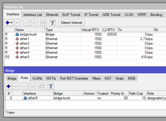
Step 2 — Add Ports to the Bridge
Add your trunk port (uplink to the switch) and your access ports (connected to end devices).
/interface bridge port
add bridge=bridge-vlans interface=ether5 pvid=1
add bridge=bridge-vlans interface=ether2 pvid=2
add bridge=bridge-vlans interface=ether3 pvid=3
add bridge=bridge-vlans interface=ether4 pvid=4
ether5is the trunk port to the Cisco switch — PVID 1 is fine here since tagged traffic will override itether2,ether3,ether4are access ports — PVID tells the bridge which VLAN to assign untagged frames arriving on each port
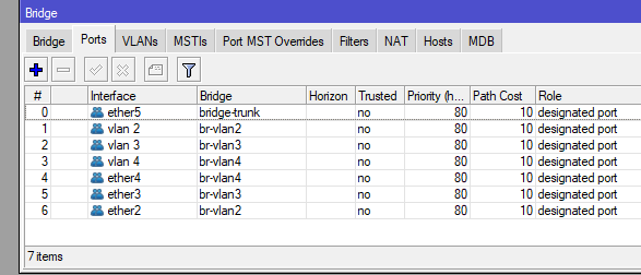
Step 3 — Configure the VLAN Table
This is where you define which VLANs are allowed on which ports, and whether each port carries them tagged or untagged.
/interface bridge vlan
add bridge=bridge-vlans vlan-ids=2 tagged=ether5,bridge-vlans untagged=ether2
add bridge=bridge-vlans vlan-ids=3 tagged=ether5,bridge-vlans untagged=ether3
add bridge=bridge-vlans vlan-ids=4 tagged=ether5,bridge-vlans untagged=ether4
Breaking this down:
- VLAN 2 is carried tagged on
ether5(the trunk to the switch) and onbridge-vlansitself (so the router can route it), and untagged onether2(the access port for VLAN 2 devices) - Same pattern for VLANs 3 and 4
Step 4 — Enable VLAN Filtering
Now that the VLAN table is in place, it’s safe to enable filtering. The bridge will start enforcing the table immediately.
/interface bridge
set bridge-vlans vlan-filtering=yes
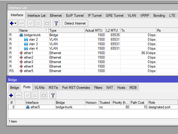
Step 5 — Create VLAN Interfaces for Routing
To route between VLANs and assign IP addresses, we need VLAN interfaces attached to the bridge.
/interface vlan
add interface=bridge-vlans name=vlan2 vlan-id=2
add interface=bridge-vlans name=vlan3 vlan-id=3
add interface=bridge-vlans name=vlan4 vlan-id=4
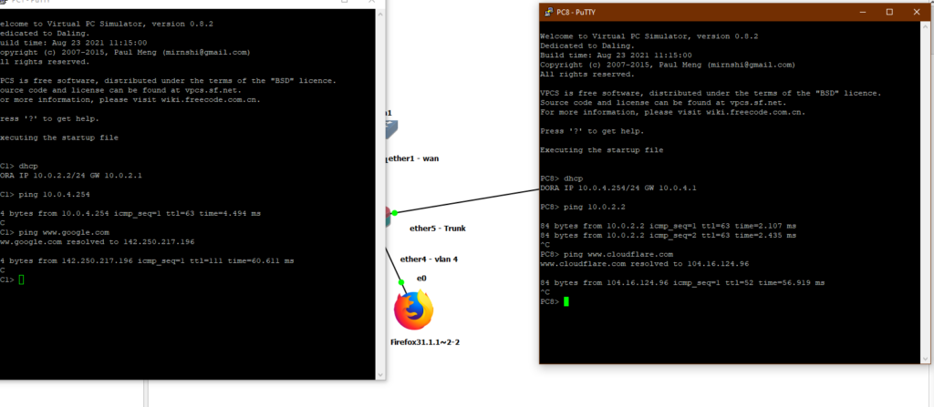
Step 6 — Assign IPs, DHCP, and NAT
This part is identical to the easy way — the IP addressing, DHCP, and NAT configuration doesn’t change, only the interfaces you assign them to.
/ip address
add address=10.0.2.1/24 interface=vlan2 network=10.0.2.0
add address=10.0.3.1/24 interface=vlan3 network=10.0.3.0
add address=10.0.4.1/24 interface=vlan4 network=10.0.4.0

/ip pool
add name=dhcp_pool0 ranges=10.0.2.2-10.0.2.254
add name=dhcp_pool1 ranges=10.0.3.2-10.0.3.254
add name=dhcp_pool2 ranges=10.0.4.2-10.0.4.254

/ip dhcp-server
add address-pool=dhcp_pool0 disabled=no interface=vlan2 name=dhcp1
add address-pool=dhcp_pool1 disabled=no interface=vlan3 name=dhcp2
add address-pool=dhcp_pool2 disabled=no interface=vlan4 name=dhcp3

/ip dhcp-client
add disabled=no interface=ether1

/ip dhcp-server network
add address=10.0.2.0/24 dns-server=10.0.2.1 gateway=10.0.2.1
add address=10.0.3.0/24 dns-server=10.0.3.1 gateway=10.0.3.1
add address=10.0.4.0/24 dns-server=10.0.4.1 gateway=10.0.4.1

/ip dns
set allow-remote-requests=yes

/ip firewall nat
add action=masquerade chain=srcnat
Easy Way vs. Proper Way — At a Glance
| Easy Way | Bridge VLAN Filtering | |
|---|---|---|
| Bridges needed | One per VLAN + one trunk | One total |
| Interface list size | Grows fast | Clean and minimal |
| Adding a new VLAN | 3+ commands, new bridge | 2 commands |
| CPU usage | Higher (software per bridge) | Lower (single bridge path) |
| Switch chip offload | No | Yes (on supported hardware) |
| Troubleshooting | Multiple bridges to check | One VLAN table to check |
| Good for learning | ✅ | After you know the basics |
| Good for production | ❌ | ✅ |
A Few Things Worth Knowing
PVID must match the VLAN table. If a port’s PVID doesn’t have a corresponding untagged entry in the VLAN table, untagged frames arriving on that port will be dropped. Double-check both match — it’s the most common source of “why isn’t this device getting an IP” confusion.
The bridge itself must be tagged in the VLAN table for routing to work. That’s what the bridge-vlans entries in Step 3 are for. If you forget this, inter-VLAN routing fails silently — devices get DHCP but can’t reach other VLANs or the internet.
This configuration assumes a clean slate. If you’re adapting this to an existing bridge that already has ports and traffic, take care — enabling VLAN filtering mid-session will drop everything that isn’t covered by the VLAN table. Test in a lab or during a maintenance window.
Final Thoughts
Once you’ve done it a few times, bridge VLAN filtering is actually simpler to manage than the easy way — there’s just less of everything. The learning curve is the VLAN table concept, which takes a bit of getting used to if you’re new to it.
If Part 1 got your VLANs working and you understand why each piece is there, you’re ready for this. The configuration is a bit more deliberate, but the payoff in cleanliness and efficiency is worth it.