
When you start working with MikroTik, VLANs can feel intimidating — especially if you’re coming from a Cisco background where the mental model is different. I’ve been there.
This post covers what I call the easy way: one bridge per VLAN. It’s not the most efficient method, and I wouldn’t recommend it for a production environment with many VLANs, but for a home lab or a small home network it works perfectly well and it’s straightforward to understand and troubleshoot. If you just want VLANs working without diving deep into MikroTik’s bridge VLAN filtering engine, this is your starting point.
A few things to keep in mind before we begin:
- I’m demonstrating this in GNS3 with a MikroTik router connected to a Cisco switch, but the commands work the same on real hardware.
- There’s no firewall or security configured in this lab — don’t apply this blindly to a production device without adding those first.
- I’m assuming you have a basic familiarity with the MikroTik CLI and can relate the commands to the Winbox GUI.
- We start from a clean slate with only a DHCP client on ether1.
The Lab Topology
In this scenario we have a MikroTik router connected to a Cisco switch via a trunk port. Three VLANs are configured, and devices on each VLAN can reach the internet and talk to each other through the router.
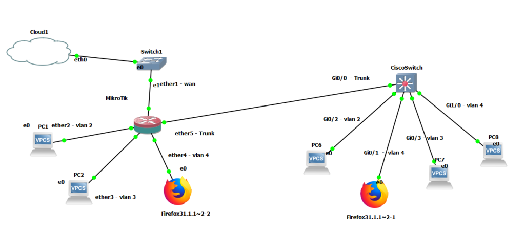
Why one bridge per VLAN?
MikroTik’s more advanced VLAN method uses a single bridge with VLAN filtering enabled — cleaner, more scalable, and better for CPU. The method in this post creates a separate bridge for each VLAN instead, which is simpler to visualize and configure but doesn’t scale well beyond a handful of VLANs. For a home lab with 3-4 VLANs, the difference is negligible.
Step 1 — Create the Trunk Bridge
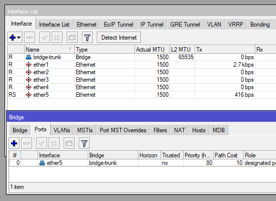
Instead of attaching VLANs directly to a physical interface, I prefer to create a bridge for the trunk port. This gives you flexibility to add more trunk ports later without restructuring everything.
/interface bridge
add name=bridge-trunk

/interface bridge port
add bridge=bridge-trunk interface=ether5
Here ether5 is the interface connected to the Cisco switch trunk port. After running this you should see the bridge and its port in Winbox: <img
Step 2 — Create the VLANs on the Trunk Bridge
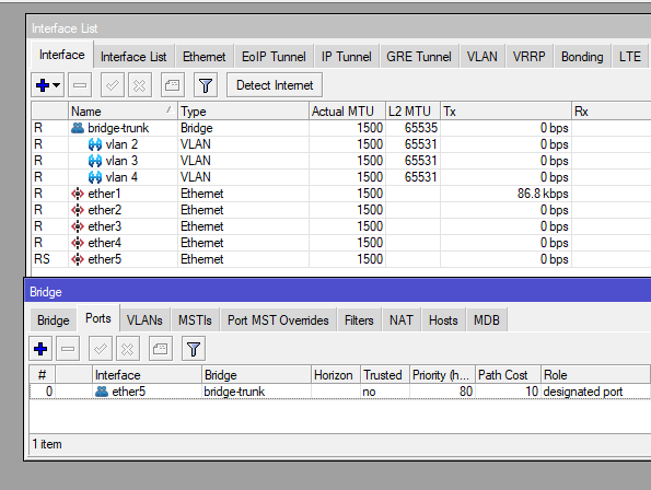
Now we create the VLAN interfaces and attach them to bridge-trunk. This tells MikroTik to expect tagged traffic for these VLAN IDs on that bridge.
/interface vlan
add interface=bridge-trunk name="vlan-2" vlan-id=2
add interface=bridge-trunk name="vlan-3" vlan-id=3
add interface=bridge-trunk name="vlan-4" vlan-id=4
Step 3 — Create a Bridge for Each VLAN
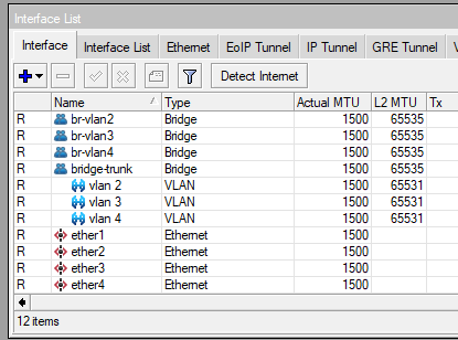
This is the “clunky” part. Each VLAN gets its own bridge. This bridge is what you’ll later attach access ports and IP addresses to.
/interface bridge
add name=br-vlan2
add name=br-vlan3
add name=br-vlan4
Step 4 — Attach VLAN Interfaces and Access Ports to Each Bridge
Now we tie everything together. Each VLAN interface goes into its corresponding bridge, and the access ports (the physical interfaces your end devices connect to) go into their respective bridges as well.
/interface bridge port
add bridge=br-vlan2 interface="vlan-2"
add bridge=br-vlan3 interface="vlan-3"
add bridge=br-vlan4 interface="vlan-4"
add bridge=br-vlan4 interface=ether4
add bridge=br-vlan3 interface=ether3
add bridge=br-vlan2 interface=ether2
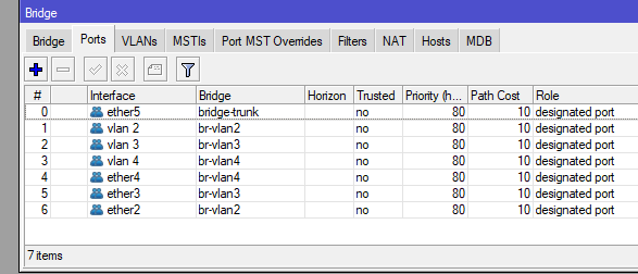
At this point the trunk and access ports are working at Layer 2. Devices on the same VLAN can reach each other. To get IP addressing, DHCP, and internet access working we need a few more steps.
Step 5 — Assign IPs, Configure DHCP, and Set Up NAT
Each VLAN bridge gets an IP address (this becomes the default gateway for devices on that VLAN), a DHCP pool, and a DHCP server. We also configure NAT so all VLANs can reach the internet.
/ip address
add address=10.0.2.1/24 interface=br-vlan2 network=10.0.2.0
add address=10.0.3.1/24 interface=br-vlan3 network=10.0.3.0
add address=10.0.4.1/24 interface=br-vlan4 network=10.0.4.0

/ip pool
add name=dhcp_pool0 ranges=10.0.2.2-10.0.2.254
add name=dhcp_pool1 ranges=10.0.3.2-10.0.3.254
add name=dhcp_pool2 ranges=10.0.4.2-10.0.4.254

/ip dhcp-server
add address-pool=dhcp_pool0 disabled=no interface=br-vlan2 name=dhcp1
add address-pool=dhcp_pool1 disabled=no interface=br-vlan3 name=dhcp2
add address-pool=dhcp_pool2 disabled=no interface=br-vlan4 name=dhcp3

/ip dhcp-client
add disabled=no interface=ether1

/ip dhcp-server network
add address=10.0.2.0/24 dns-server=10.0.2.1 gateway=10.0.2.1
add address=10.0.3.0/24 dns-server=10.0.3.1 gateway=10.0.3.1
add address=10.0.4.0/24 dns-server=10.0.4.1 gateway=10.0.4.1

/ip dns
set allow-remote-requests=yes

/ip firewall nat
add action=masquerade chain=srcnat
Result
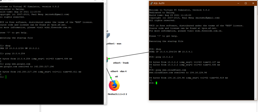
With everything in place, devices on different VLANs can communicate through the router and reach the internet — as shown here with PC1 and PC8 on opposite ends of the topology on different VLANs:
Config Files
If you want to study the full configuration or follow along in your own lab, here are the config files used in this post:
If you’d like the GNS3 lab file, send me an email and I’ll share it.
When to Use This Method — And When to Move On
If you’ve never configured VLANs before, or you’ve never done it on MikroTik specifically, this is a great way to get your feet wet. The structure is visible and tangible — you can see every bridge, every VLAN interface, every port assignment in Winbox. That transparency makes it easier to understand what’s actually happening at each layer, which is valuable when you’re learning.
That said, you should make an effort to learn the proper way once this clicks. Here’s why:
Performance. The easy way does all VLAN tagging and untagging in software on the CPU. Every packet that crosses a VLAN boundary goes through RouterOS’s bridge code. On a busy network or a router handling many VLANs, this adds up. The proper method — bridge VLAN filtering — is more efficient because there’s only one bridge in the kernel’s forwarding path instead of one per VLAN. On hardware with a built-in switch chip it can offload VLAN handling entirely to hardware, barely touching the CPU at all.
Management. The easy way grows linearly and messily. Five VLANs means five extra bridges, five VLAN interfaces, and five sets of bridge port assignments on top of your trunk bridge. Your interface list becomes a wall of entries and finding things in Winbox gets tedious. With bridge VLAN filtering, everything lives in one bridge. The VLAN table is a single clean list, and adding a new VLAN is a one-liner instead of three commands and a new bridge.
Troubleshooting. When something breaks with the easy way, you’re tracing traffic across multiple bridges. With a single bridge there’s one place to look — the bridge VLAN table and its port assignments.
The honest caveat: for a home lab with three or four VLANs and normal traffic levels, the performance difference is genuinely invisible. The management argument is the stronger one — this approach just gets unwieldy as you grow. Start here if you need to, but treat it as a stepping stone rather than a destination.